


Traffic turn signal for bicycles
Introduction
Does every project with electronic logic need a Microcontroller or Arduino to be developed? Today, many people use Microcontrollers to solve a problem.
Is there an error in this? None! But the project may have increased costs and make it difficult to sell to end consumers. It is for this reason that we need to look for simple and viable solutions.
In the project presented in this article we will present this to you. In it we will show you how to implement a simple solution and investing little money with electronic components.
In this PCBWay article you will learn how to develop a sign to signal the change of direction of cyclists in traffic.
All files are allowed in this link. If you are smart, you can use it to create some PCBs and sell it for people or stores interested in ciclism.
Every year, several cyclists are involved in traffic accidents due to other people's mistakes or because they do not use adequate signage. This ends up causing many deaths and leaving people unable to get around.
To avoid this problem, PCBWay supported the development of a lane change signal for cyclists. In addition to providing security, the project is open and you can use it to sell to other cyclists.
It uses few electronic components and is easy to assemble. Now, let's understand the complete structure of the electronic circuit.
Electronic Circuit of the Turn Signal for Cyclists
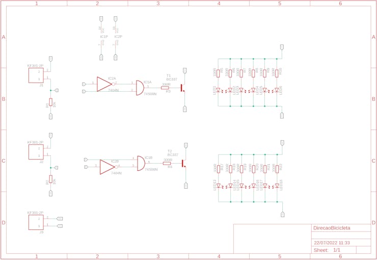
The figure below shows the electronic circuit of the project.
How does the electronic circuit work?
The electronic circuit is formed by a group of LEDs that will be used to signal that a cyclist will turn left or right. This will be done through the use of two buttons.
Each button will be connected to the handlebars of the bicycle and will be connected to the circuit on the board through wires.
The signal from each button is sent to the logic circuit input of the electronic board.
This circuit was developed using combinational logic. Through logic gates it was possible to implement the complete solution for this circuit.
What logic was implemented?
The combinational circuit is formed by two inputs, which are the left button and the right button.
Combinational logic works as follows:
- Turn off all LEDs when buttons are not pressed,
- Turn on the left LEDs when the left button is pressed,
- Turn on the right LEDs when the right button is pressed, and
- Turn off all LEDs when both buttons are pressed.
From this logic, a combinational table was created to relate the digital inputs with their respective digital outputs. See the table below.
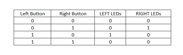
This table presents the combinations of inputs and their respective digital outputs. From this table, a Boolean logic expression was developed and we set up the logic circuit below.
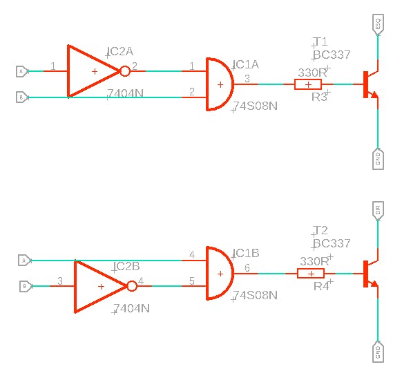
At the output of each circuit, transistors were placed to switch the set of 6 LEDs to signal left and right.
The group of LEDs is shown in the figure below.

Each group of LEDs was connected to the collector terminal of each transistor. This allowed to drive all the LEDs through a single transistor.
Finally, we insert 3 screw connectors into the electronic circuit.
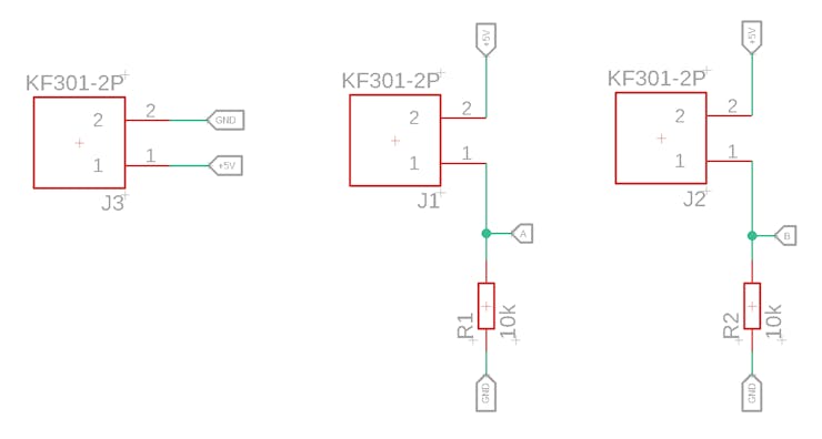
We have a connector for powering the electronic project with a +5V battery. The other 2 connectors will be used to connect the buttons. A 10kR pull-down resistor was inserted for each button.
Finally, we finalized the electronic schematic design and developed the layout of the printed circuit board. See the result in the figure below.
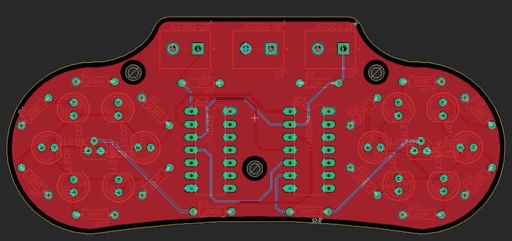
3 holes were inserted in the electronic board to facilitate the fixing of the board on the bicycle frame or in another place desired by the cyclist.
The following is the full 3D view of the board in Fusion 360 software.
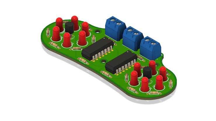
This electronic board is easy to assemble and you can find the components in any store in your city, as THT electronic components were used and this facilitates the board assembling process for any user who wants to use it.
Develop with Microcontroller or Logic Circuit?
As you can see, we implemented the entire electronic circuit with combinational logic and used only 2 digital integrated circuits to solve this problem.
The same circuit could be developed and programmed by a Microcontroller, but, as mentioned before, the costs are high and the profit margin in case of sales is reduced.
That's why we carried out a preliminary analysis of the problem and built it in a simple, cheap and viable way to be assembled by anyone.
For less than $2 you can assemble an electronic board and sell it to people interested in protecting themselves during cycling activities while in transit.
Take advantage now and order 10 electronic boards on PCBWay for $5.

Traffic turn signal for bicycles
*PCBWay community is a shared platform and we are not responsible for any design issues.


- Comments(0)
- Likes(3)
 More by silicioslab
-
 WS2812B RGB LED Controller with ESP8266 via WiFi
IntroductionWS2812b addressable RGB LEDs are devices widely used in lighting projects. They are foun...
WS2812B RGB LED Controller with ESP8266 via WiFi
IntroductionWS2812b addressable RGB LEDs are devices widely used in lighting projects. They are foun...
-
 Electronic Board for Cutting Electrical Power to Devices and Machines
IntroductionAn energy saving system for cutting electrical energy in machines is a fundamental piece...
Electronic Board for Cutting Electrical Power to Devices and Machines
IntroductionAn energy saving system for cutting electrical energy in machines is a fundamental piece...
-
 PCB Board Home Automation with ESP8266
IntroductionThe incorporation of the ESP8266 module into home automation represents a significant ad...
PCB Board Home Automation with ESP8266
IntroductionThe incorporation of the ESP8266 module into home automation represents a significant ad...
-
 Dedicated Control Board for Mobile Robots with Wheels
IntroductionFor a long time we developed several prototypes and teaching kits of mobile robots and w...
Dedicated Control Board for Mobile Robots with Wheels
IntroductionFor a long time we developed several prototypes and teaching kits of mobile robots and w...
-
 Traffic turn signal for bicycles
IntroductionDoes every project with electronic logic need a Microcontroller or Arduino to be develop...
Traffic turn signal for bicycles
IntroductionDoes every project with electronic logic need a Microcontroller or Arduino to be develop...
-
 Mini Arduino with ATTINY85
Do you know the ATTINY85 microcontroller? This article has news and a gift for you. Many people deve...
Mini Arduino with ATTINY85
Do you know the ATTINY85 microcontroller? This article has news and a gift for you. Many people deve...
-
 Christmas Tree
The tree used to signal light of Christmas.
Christmas Tree
The tree used to signal light of Christmas.
-
 Activating loads with relay via WiFi with ESP8266
IntroductionDo you want an electronic board for activating loads via WiFi that is safe against surge...
Activating loads with relay via WiFi with ESP8266
IntroductionDo you want an electronic board for activating loads via WiFi that is safe against surge...
-
 Hospital Water Tank Monitoring via the Internet
IntroductionOne of the elements of great importance for the functioning of hospitals is water. It is...
Hospital Water Tank Monitoring via the Internet
IntroductionOne of the elements of great importance for the functioning of hospitals is water. It is...
-
 ESP32 IoT Development Board with Monitoring Battery System
IntroductionToday I want to tell you what one of the biggest problems is in electronic projects invo...
ESP32 IoT Development Board with Monitoring Battery System
IntroductionToday I want to tell you what one of the biggest problems is in electronic projects invo...
-
 Control Board for 6 Servomotors based on Arduino for Robotic projects
In the last few weeks we started developing this robotic arm. It is made up of 5 servomotors. To fac...
Control Board for 6 Servomotors based on Arduino for Robotic projects
In the last few weeks we started developing this robotic arm. It is made up of 5 servomotors. To fac...
-
 PCBWay Standalone Arduino
IntroductionDo you know how the basic circuit of an Arduino works? Every Arduino has a minimum circu...
PCBWay Standalone Arduino
IntroductionDo you know how the basic circuit of an Arduino works? Every Arduino has a minimum circu...
-
 Human Machine Interface based in Arduino with ATMEGA328P Standalone
Several commercial and industrial applications require a screen system to present data and receive p...
Human Machine Interface based in Arduino with ATMEGA328P Standalone
Several commercial and industrial applications require a screen system to present data and receive p...
-
 Small Low Cost Circuit Deveelopment Board for Prototypes
In recent years I have developed numerous prototypes with Arduino. During these creations, something...
Small Low Cost Circuit Deveelopment Board for Prototypes
In recent years I have developed numerous prototypes with Arduino. During these creations, something...
-
 Intruder alert system with SMS
In several places, we must monitor the security of spaces and prevent intruders from entering prohib...
Intruder alert system with SMS
In several places, we must monitor the security of spaces and prevent intruders from entering prohib...
-
 Mini Arduino Laboratory
I have worked in teaching laboratories for over 10 years. One of the great difficulties in these spa...
Mini Arduino Laboratory
I have worked in teaching laboratories for over 10 years. One of the great difficulties in these spa...
-
 PCBWay WiFi ESPBoard-01
Can you imagine controlling any device over the internet? Lamps, water pumps for irrigation, gate dr...
PCBWay WiFi ESPBoard-01
Can you imagine controlling any device over the internet? Lamps, water pumps for irrigation, gate dr...
-
 Educational Robot for Children
All areas of knowledge such as sciences, human or biological, have their respective importance. With...
Educational Robot for Children
All areas of knowledge such as sciences, human or biological, have their respective importance. With...
-
-
Open Source Very Large Stick - Freejoy & MMjoy2 breakout board
563 0 0 -
RF Control training board for students based on ESP32 C3
747 0 2 -
-
KINETIC COASTERS with a TWIST! Laser or 3D Print some DIY Magic
646 0 1 -
RPI - 8 IO PLC With ATTiny85 Watch Dog
558 0 1 -
Nintendo Famicom HVC-001 Controller Shells
668 0 1 -
COMMODORE 128 DIAGNOSTIC REV.785260 KEYBOARD DONGLE
622 0 4


