


|
Autodesk Fusion 360Autodesk
|
|

|
EagleAutodesk
|
Dedicated Control Board for Mobile Robots with Wheels
Introduction
For a long time we developed several prototypes and teaching kits of mobile robots and we always used different modules to build them.
Among these modules, we highlight: module to drive motors, module TP4056 to charge the project's batteries, an Arduino board and a shield for connecting the wires to the Arduino's digital inputs.
This amount of modules often generates problems with bad connections and also makes connections more complex, with more wires. Also, they are not feasible to build a prototype or commercial product.
After all, what to do to reduce the number of modules in the construction of mobile robot teaching kits?
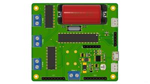
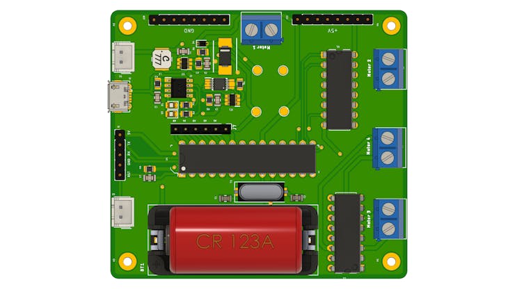
Based on this problem, we developed a circuit board with several features that will allow you to control your mobile robot. See the picture below.
The files for this board are available for download from the PCBWay website. Take advantage now, visit the link, register and get a $5 coupon for you to win 10 free units of this electronic board.
What features have been implemented in this electronic board?
Below we have all the functionalities implemented in the electronic board.
- Charging system for Li-Ion battery with IC TP4056,
- DC-DC Boost Converter Circuit with 6V output,
- L293D Driver Circuit for the Motors, and
- Arduino Standalone Circuit with the ATMEGA328P.
Below we will present in detail all these functionalities implemented from the electronic schematic of the project.
Control Board Electronic Schematic
The electronic circuit was divided into 4 parts: battery charging circuit, motor drive drivers, ATMEGA328P control circuit, circuit connectors and fixing holes. Below we have the electronic schematic of the project.
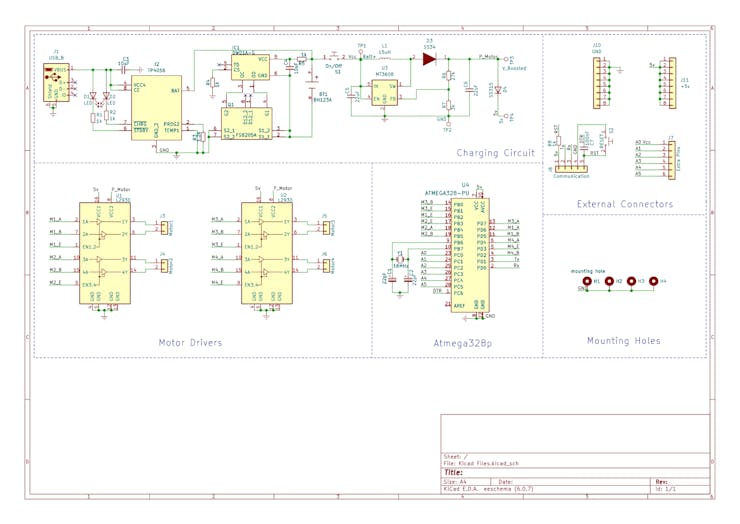
Next, we will discuss each part of the circuit and how it works in the mobile robot control process.
Mobile Robot Battery Charging Circuit
Many users who program mobile robots constantly need to remove the batteries from the project to charge it. This process requires opening the robot and an external charger for charging.
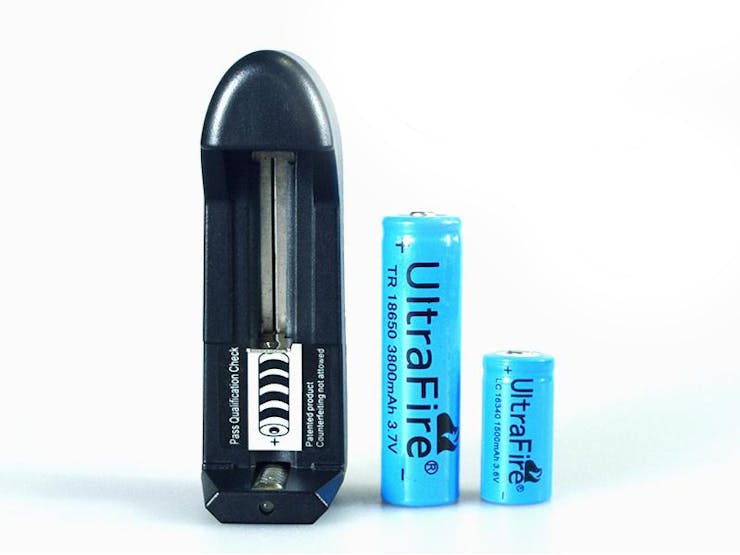
In addition, 2 18650 batteries are usually used to supply a voltage of 7.4V for project power. This requires more internal space and financial cost of 2 batteries.
How to solve this problem?
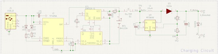
The first step for this was to create a circuit for charging Li-Ion battery with IC TP4056. The circuit structure is shown in the figure below.
Before implementing the charging circuit, we want to use only 1 3.7V Li-Ion 16340 battery to power the project.
In addition to avoiding the use of 2 18650 batteries, it will allow us to reduce the space consumed in the electronic board structure and in the prototype.
However, how do we supply the ATMEGA328P chip with +5V and the motors with +6V?
This question will be answered below.
First, we implement the charging circuit with IC TP4056. It will be used to control and transfer energy to the 16340 Li-Ion battery.
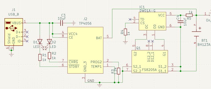
In addition to it, we use the DW01-A CI to ensure safety against overloads and short circuits during the battery charging process. In the electronic diagram of the figure above we have the battery represented by the BT1 element.
After the battery we insert a JST connector to insert an ON/OFF button. This allows you to turn the project control circuit on and off. Now, let's go back and answer the previous question: how to power the ATMEGA328P chip with +5V and the motors with +6V?
This lifting process is done through the circuit below. What circuit is this and how does it work?
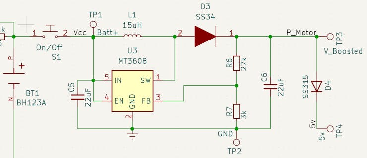
The circuit above is a boost type DC-DC converter. It has the purpose of raising the input DC voltage to another DC voltage level at the output.
For this project we are raising the battery voltage from +3.7V to +6V.
All of the above elements were calculated to provide this voltage. The MT3608 CHIP is the circuit's STEP-UP converter. Access the datasheet through this link.
At the output of the +6V power circuit, we insert an SS315 diode to provide a voltage drop of 0.95V. This allows us to obtain a voltage of approximately +5V to power the control circuit of the ATMEGA328P.
Control Circuit with ATMEGA328P Microcontroller
The ATMEGA328P Microcontroller circuit is shown below.
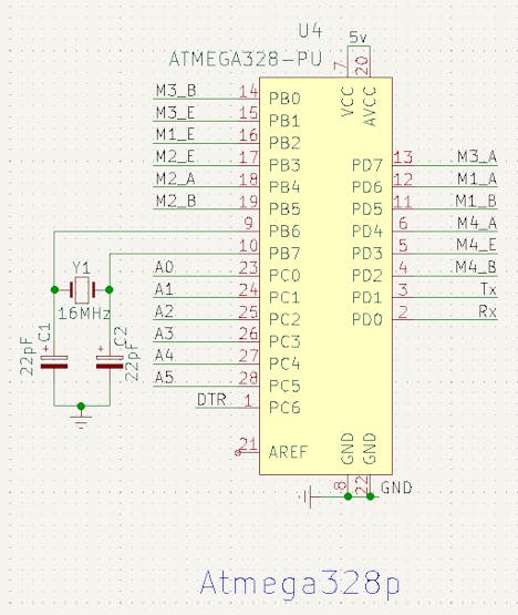
Several microcontroller digital pins were used to control the pins of the 2 L293D drivers.
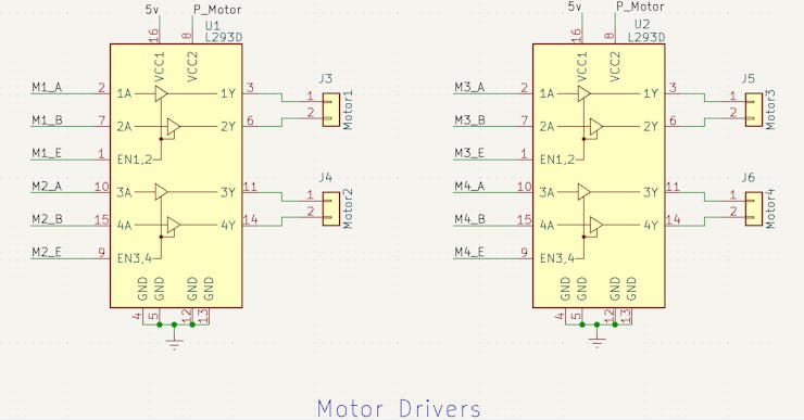
L293D Driver for the Motor
Next, we have the electronic schematic shown in the figure below. Each driver was used to control 2 motors. This therefore allows the electronic board to be used to control 2- to 4-wheel mobile robots.
Finally, we created a way to monitor the project's power battery.
Mechanism for Monitoring Battery Voltage
On several devices, such as notebooks and cell phones, for example, it is possible to observe the battery capacity level. This allows us to know when is the ideal time to carry out a new load.
With that in mind, we created a means to implement this. To do this, we connect the battery output to the A0 terminal of the ATMEGA328P Microcontroller.
From the input voltage it is possible to create a function and inform the battery capacity between 0% and 100%. We have determined a minimum voltage of 3..2V and a maximum voltage of 4.2V for 100%. Whenever the battery is close to this value, it is possible to generate an alert to the user to charge the project's battery.
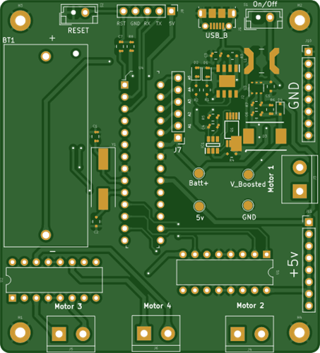
Finally, we provide some power and connection pins to the ATMEGA328P Microcontroller pins.
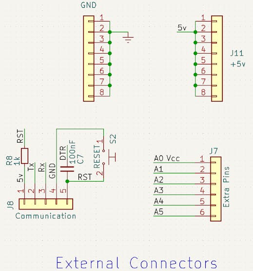
Pins for Power and Connection of other Devices
How to connect an ultrasonic sensor to this electronic board or an extra button, for example?
This can be done through the male headers connector pins shown below.
In total there are 4 connectors. Among them we have:
1 connector with voltage potential 0V,
1 connector with voltage potential of +5V, and
1 connector with access to pins A1, A2, A3, A4, and A5.
From these 3 connectors we can connect several sensors and other devices that will facilitate the navigation of the mobile robot.
In addition to these pins, we have a connector to transfer the code to the ATMEGA328P Microcontroller with access to the +5V, GND, TX, RX, and RESET pins.
See electronic schematic below.
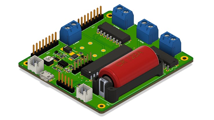
Below we present the complete structure of the electronic board of the project.
Electronic Board Structure for Mobile Robot Control
All images are inserted in this project.
All files for this project are available in this PCBWay Shared Projects Comunitye. You will have access to the following files:
- Electronic schematic,
- Gerber file,
- List of materials,
- 3D file of the electronic board for prototyping, and
- Pick and Place file for SMD assembly.
Future Updates
All files are available for download and you can get 10 free PCBWay units. To earn the $5 coupon and receive the 10 units you must access this link, create your account and order your plates for free.
In future updates we will develop a new version with a USB flashing circuit to facilitate the direct transfer of code from the computer to the development board.
All future PCB updates are available soon at the end of this article.Take advantage now and get 10 free units of this Arduino at your home. Click here and enjoy.
Dedicated Control Board for Mobile Robots with Wheels
*PCBWay community is a shared platform and we are not responsible for any design issues.


- Comments(0)
- Likes(1)
More by silicioslab
-
 WS2812B RGB LED Controller with ESP8266 via WiFi
IntroductionWS2812b addressable RGB LEDs are devices widely used in lighting projects. They are foun...
WS2812B RGB LED Controller with ESP8266 via WiFi
IntroductionWS2812b addressable RGB LEDs are devices widely used in lighting projects. They are foun...
-
 Electronic Board for Cutting Electrical Power to Devices and Machines
IntroductionAn energy saving system for cutting electrical energy in machines is a fundamental piece...
Electronic Board for Cutting Electrical Power to Devices and Machines
IntroductionAn energy saving system for cutting electrical energy in machines is a fundamental piece...
-
 PCB Board Home Automation with ESP8266
IntroductionThe incorporation of the ESP8266 module into home automation represents a significant ad...
PCB Board Home Automation with ESP8266
IntroductionThe incorporation of the ESP8266 module into home automation represents a significant ad...
-
 Dedicated Control Board for Mobile Robots with Wheels
IntroductionFor a long time we developed several prototypes and teaching kits of mobile robots and w...
Dedicated Control Board for Mobile Robots with Wheels
IntroductionFor a long time we developed several prototypes and teaching kits of mobile robots and w...
-
 Traffic turn signal for bicycles
IntroductionDoes every project with electronic logic need a Microcontroller or Arduino to be develop...
Traffic turn signal for bicycles
IntroductionDoes every project with electronic logic need a Microcontroller or Arduino to be develop...
-
 Mini Arduino with ATTINY85
Do you know the ATTINY85 microcontroller? This article has news and a gift for you. Many people deve...
Mini Arduino with ATTINY85
Do you know the ATTINY85 microcontroller? This article has news and a gift for you. Many people deve...
-
 Christmas Tree
The tree used to signal light of Christmas.
Christmas Tree
The tree used to signal light of Christmas.
-
 Activating loads with relay via WiFi with ESP8266
IntroductionDo you want an electronic board for activating loads via WiFi that is safe against surge...
Activating loads with relay via WiFi with ESP8266
IntroductionDo you want an electronic board for activating loads via WiFi that is safe against surge...
-
 Hospital Water Tank Monitoring via the Internet
IntroductionOne of the elements of great importance for the functioning of hospitals is water. It is...
Hospital Water Tank Monitoring via the Internet
IntroductionOne of the elements of great importance for the functioning of hospitals is water. It is...
-
 ESP32 IoT Development Board with Monitoring Battery System
IntroductionToday I want to tell you what one of the biggest problems is in electronic projects invo...
ESP32 IoT Development Board with Monitoring Battery System
IntroductionToday I want to tell you what one of the biggest problems is in electronic projects invo...
-
 Control Board for 6 Servomotors based on Arduino for Robotic projects
In the last few weeks we started developing this robotic arm. It is made up of 5 servomotors. To fac...
Control Board for 6 Servomotors based on Arduino for Robotic projects
In the last few weeks we started developing this robotic arm. It is made up of 5 servomotors. To fac...
-
 PCBWay Standalone Arduino
IntroductionDo you know how the basic circuit of an Arduino works? Every Arduino has a minimum circu...
PCBWay Standalone Arduino
IntroductionDo you know how the basic circuit of an Arduino works? Every Arduino has a minimum circu...
-
 Human Machine Interface based in Arduino with ATMEGA328P Standalone
Several commercial and industrial applications require a screen system to present data and receive p...
Human Machine Interface based in Arduino with ATMEGA328P Standalone
Several commercial and industrial applications require a screen system to present data and receive p...
-
 Small Low Cost Circuit Deveelopment Board for Prototypes
In recent years I have developed numerous prototypes with Arduino. During these creations, something...
Small Low Cost Circuit Deveelopment Board for Prototypes
In recent years I have developed numerous prototypes with Arduino. During these creations, something...
-
 Intruder alert system with SMS
In several places, we must monitor the security of spaces and prevent intruders from entering prohib...
Intruder alert system with SMS
In several places, we must monitor the security of spaces and prevent intruders from entering prohib...
-
 Mini Arduino Laboratory
I have worked in teaching laboratories for over 10 years. One of the great difficulties in these spa...
Mini Arduino Laboratory
I have worked in teaching laboratories for over 10 years. One of the great difficulties in these spa...
-
 PCBWay WiFi ESPBoard-01
Can you imagine controlling any device over the internet? Lamps, water pumps for irrigation, gate dr...
PCBWay WiFi ESPBoard-01
Can you imagine controlling any device over the internet? Lamps, water pumps for irrigation, gate dr...
-
 Educational Robot for Children
All areas of knowledge such as sciences, human or biological, have their respective importance. With...
Educational Robot for Children
All areas of knowledge such as sciences, human or biological, have their respective importance. With...
-
-
Open Source Very Large Stick - Freejoy & MMjoy2 breakout board
563 0 0 -
RF Control training board for students based on ESP32 C3
748 0 2 -
-
KINETIC COASTERS with a TWIST! Laser or 3D Print some DIY Magic
646 0 1 -
RPI - 8 IO PLC With ATTiny85 Watch Dog
558 0 1 -
Nintendo Famicom HVC-001 Controller Shells
669 0 1 -
COMMODORE 128 DIAGNOSTIC REV.785260 KEYBOARD DONGLE
623 0 4


