


Gerber_PCB_PCB_CPU789_2_2024-01-05 (1)_2024-01-10
A Student designed ESP8266 Dev Board

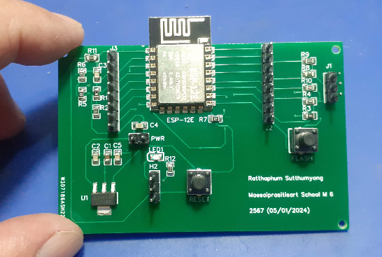
This is a student-designed ESP8266 Dev board. This project came along after I challenged some final-year students at our local high school to try to design their own PCBs. They had recently assisted me in a collaboration with the Mushroom House Controller project, and while we were talking about electronics, the idea of a challenge came up, to stimulate some interaction.
One of them was extremely confident that he could do it, providing that I gave him a schematic. I complied, and he spent the next week hacking away on the EDA software. When i saw him again, he very proudly handed me a USB flash drive, containing the EDA design, but no schematic! Oh well, let us take a chance and see what happens… I mean, how bad could it be…
I took a good look at the design, making sure that it was at least electrically sound, with all the connections made to the right components, in the right way.
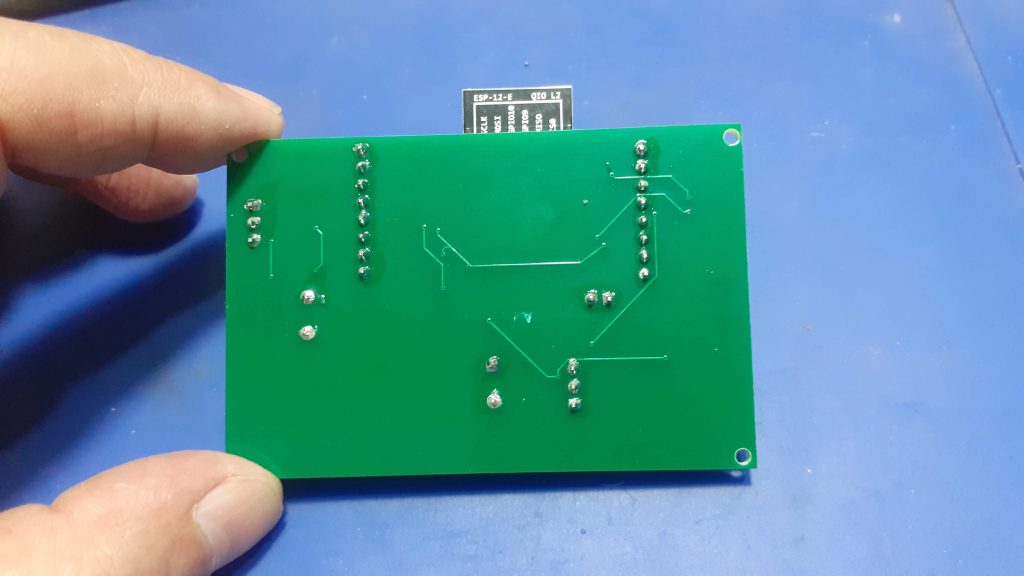
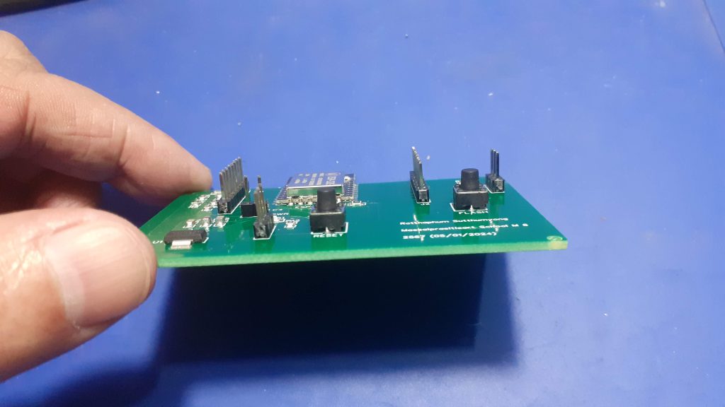
That part all passed, but, as we can clearly see, the layout could be very much improved. I decided to NOT change anything on the PCB, to keep the work original.
Manufacturing the PCB
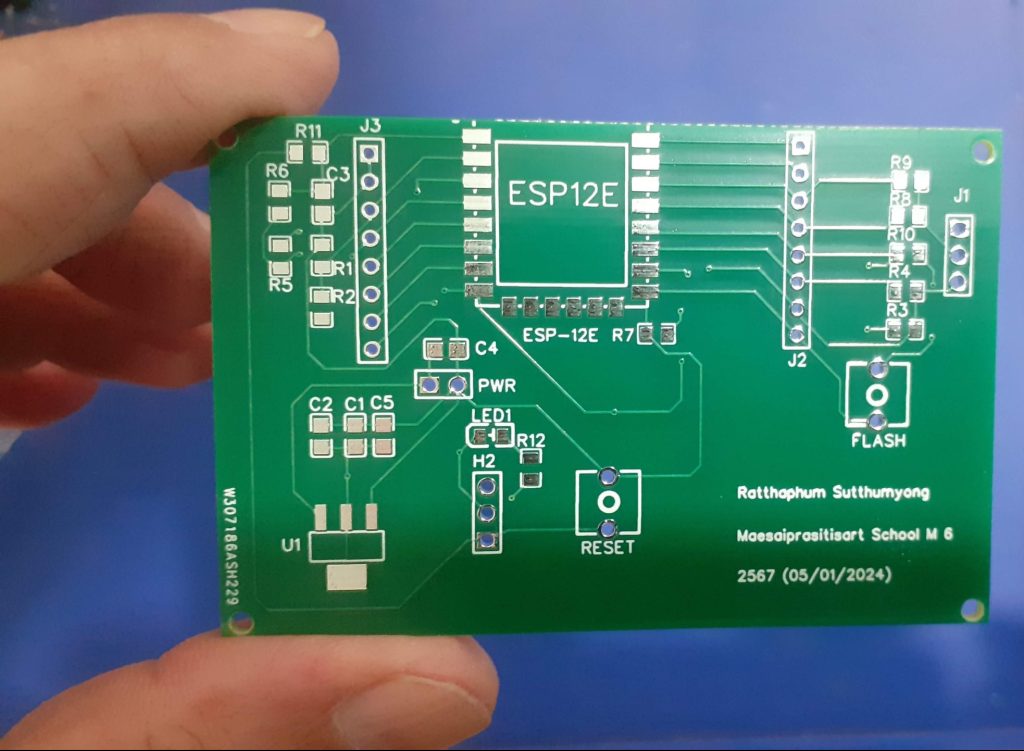
The PCB, together with a stencil, arrived from PCBWay on about the 15th of this month.
I choose PCBWay for my PCB manufacturing. Why? What makes them different from the rest?
PCBWay‘s business goal is to be the most professional PCB manufacturer for prototyping and low-volume production work in the world. With more than a decade in the business, they are committed to meeting the needs of their customers from different industries in terms of quality, delivery, cost-effectiveness and any other demanding requests. As one of the most experienced PCB manufacturers and SMT Assemblers in China, they pride themselves to be our (the Makers) best business partners, as well as good friends in every aspect of our PCB manufacturing needs. They strive to make our R&D work easy and hassle-free.
How do they do that?
PCBWay is NOT a broker. That means that they do all manufacturing and assembly themselves, cutting out all the middlemen, and saving us money.
PCBWay’s online quoting system gives a very detailed and accurate picture of all costs upfront, including components and assembly costs. This saves a lot of time and hassle.
PCBWay gives you one-on-one customer support, that answers you in 5 minutes ( from the Website chat ), or by email within a few hours ( from your personal account manager). Issues are really resolved very quickly, not that there are many anyway, but, as we are all human, it is nice to know that when a gremlin rears its head, you have someone to talk to who will do his/her best to resolve your issue as soon as possible.
Find out more here
Assembly
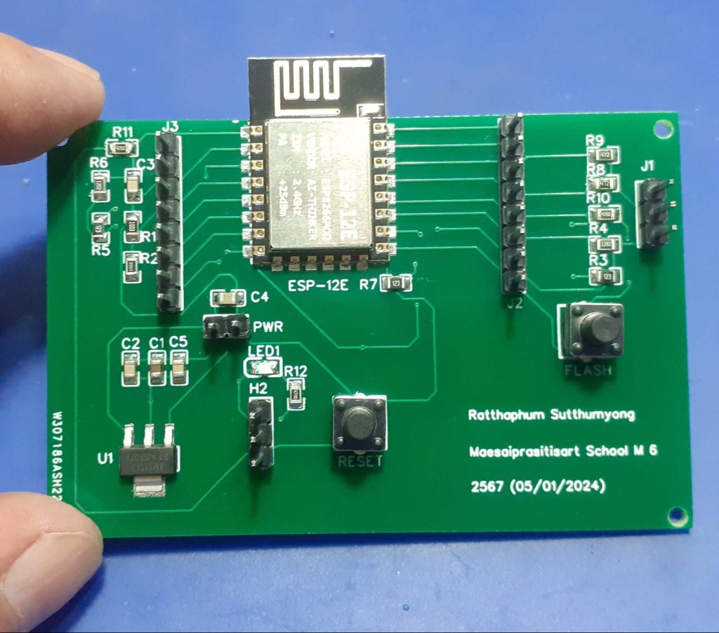
The PCB was assembled with help of a stencil.
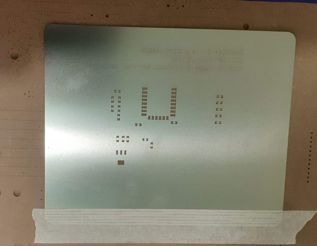
Technically, this PCB does not actually need it, as the components are large enough to manually place solder paste. This being a student project, I did however choose to get the stencil to try and assure the best possible chance of success..
Placing components only took a few minutes, after which the PCB was reflowed with hot air – no need for a hotplate here!
Through-hole components took only another few minutes to solder into place, and then testing could commence.
My thoughts – a very “gentle” critique
The board could be smaller, but due to the fact that this is a “very first PCB ever” and also a first SMD PCB at that, I can understand that it may still be quite difficult to understand how small the components really are, as well as lay them out properly.
Components are mostly all over the board, without a clear “group by function” kind of mindset. This once again comes back to experience.
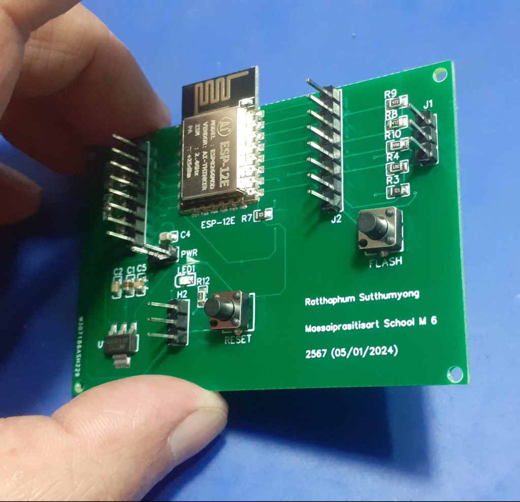
GPIO pins are not notated. This will really make the board difficult to use.
The power supply input is in the center of the PCB. This is definitely not ideal.
In general, track sizes could have been bigger, especially on the Power and Ground lines. No ground plane was poured on either layer.
So does it work?
Yes, surprisingly it does. We shall see more of it in the near future, when I task the creator with using it to perform some task. That way, he can experience first hand the difficulties of the design, and also learn practically why certain things need to be improved.
 Author makeriot2020Posted on January 26, 2024Categories Custom PCB Design, ESP8266Tags Electronics, ESP8266 Edit "A Student designed ESP8266 Dev Board"
Gerber_PCB_PCB_CPU789_2_2024-01-05 (1)_2024-01-10
*PCBWay community is a shared platform and we are not responsible for any design issues.


- Comments(0)
- Likes(0)
More by Jean Redelinghuys MakerIoT2020
-
 PCB_MCP23008_2023-10-08
MCP23008 BreakoutI designed this breakout to assist me during prototyping my next version of the “RP...
PCB_MCP23008_2023-10-08
MCP23008 BreakoutI designed this breakout to assist me during prototyping my next version of the “RP...
-
 PCB_XiaoRP2040-Mouse-REV2
Xiao RP2040 Joystick Mouse – revision 2.00Revision 1.0 of the ProjectOver the last few months, I hav...
PCB_XiaoRP2040-Mouse-REV2
Xiao RP2040 Joystick Mouse – revision 2.00Revision 1.0 of the ProjectOver the last few months, I hav...
-
 Multi Purpose IO Card
Multi-Purpose IO CardWhen we are working on a prototype, we always need access to pushbuttons, encod...
Multi Purpose IO Card
Multi-Purpose IO CardWhen we are working on a prototype, we always need access to pushbuttons, encod...
-
 Variable Voltage Power Module
Powering electronics projects are always challenging. This Variable vol...
Variable Voltage Power Module
Variable Voltage Power ModulePowering electronics projects are always challenging. This Variable vol...
-
 I2C Matrix Keypad
An I2C Matrix KeypadThe completed I2C Matrix KeypadIn a previous post this month I introduced my 4×4...
I2C Matrix Keypad
An I2C Matrix KeypadThe completed I2C Matrix KeypadIn a previous post this month I introduced my 4×4...
-
 ESP32-S Development Board, in "Arduino Uno" form factor
UPDATE 24/06/2023:This board now has a Hardware Revision 2.0 available. It is the same board but wit...
ESP32-S Development Board, in "Arduino Uno" form factor
UPDATE 24/06/2023:This board now has a Hardware Revision 2.0 available. It is the same board but wit...
-
 W307186ASC94_Gerber_PCB_USB-Ports
USB Power Supply ModuleUSB Ports are quite handy to power all our day-to-day electronic devices, but...
W307186ASC94_Gerber_PCB_USB-Ports
USB Power Supply ModuleUSB Ports are quite handy to power all our day-to-day electronic devices, but...
-
 Atmega 328P based PWM controller Card
ATMega 328P Based PWM controller CardAs part of my recent ESP-12E I2C Base Board project, I designed...
Atmega 328P based PWM controller Card
ATMega 328P Based PWM controller CardAs part of my recent ESP-12E I2C Base Board project, I designed...
-
 W307186ASC71_Gerber_PCB_ESP-Now Remote
Today we will look at the remote control unit for the Robotic Toy Car – Part 6.The project is close ...
W307186ASC71_Gerber_PCB_ESP-Now Remote
Today we will look at the remote control unit for the Robotic Toy Car – Part 6.The project is close ...
-
 W307186ASV69_Gerber_PCB_Robot-Car-MCU-Board Prototype
In our last project, we started working on repurposing an old toy car. In this part, Robot Toy Car –...
W307186ASV69_Gerber_PCB_Robot-Car-MCU-Board Prototype
In our last project, we started working on repurposing an old toy car. In this part, Robot Toy Car –...
-
 W307186ASV62_Gerber_PCB_DUAL-H-Bridge
by makeriot2020 on May 27, 2022Many of us have old toys laying around the house, they belong to ou...
W307186ASV62_Gerber_PCB_DUAL-H-Bridge
by makeriot2020 on May 27, 2022Many of us have old toys laying around the house, they belong to ou...
-
 CAN-BUS Breakout
Breadboard Compatible CAN-BUS Breakout ModuleWhat is this:Some of us have already used the commonly ...
CAN-BUS Breakout
Breadboard Compatible CAN-BUS Breakout ModuleWhat is this:Some of us have already used the commonly ...
-
 RA-02 Breakout with Level converters
Breadboard and beginner-friendly RA-02 Breakout ModuleMost Makers and electronics enthusiasts may al...
RA-02 Breakout with Level converters
Breadboard and beginner-friendly RA-02 Breakout ModuleMost Makers and electronics enthusiasts may al...
-
 ATMEGA328P Module with integrated LoRa and CAN Bus
ATMEGA328P Module with integrated LoRa and CAN-BUSINTRODUCTIONIn my quest to perfect my LoRa telemet...
ATMEGA328P Module with integrated LoRa and CAN Bus
ATMEGA328P Module with integrated LoRa and CAN-BUSINTRODUCTIONIn my quest to perfect my LoRa telemet...
-
 Sx127x-Ra-02-Test-Module with ATMEGA328P-AU
SX127x LoRa/FSK/OOK Prototype Radio BoardI recently had a requirement to do some automation/telemetr...
Sx127x-Ra-02-Test-Module with ATMEGA328P-AU
SX127x LoRa/FSK/OOK Prototype Radio BoardI recently had a requirement to do some automation/telemetr...
-
 USB-ASP Programmer ATMEGA8
Build your own USB-ASP Programmer CloneBymakeriot2020 FEB 21, 2022 Arduino, ASP programmerUsing mor...
USB-ASP Programmer ATMEGA8
Build your own USB-ASP Programmer CloneBymakeriot2020 FEB 21, 2022 Arduino, ASP programmerUsing mor...
-
 Gerber_PCB_Soil-Moisture-project-M5
A Simple IoT Plant Watering SolutionThis is a Simple IoT Plant Watering Solution, done as another co...
Gerber_PCB_Soil-Moisture-project-M5
A Simple IoT Plant Watering SolutionThis is a Simple IoT Plant Watering Solution, done as another co...
-
 Gerber_PCB_PCB_CPU789_2_2024-01-05 (1)_2024-01-10
A Student designed ESP8266 Dev BoardThis is a student-designed ESP8266 Dev board. This project came ...
Gerber_PCB_PCB_CPU789_2_2024-01-05 (1)_2024-01-10
A Student designed ESP8266 Dev BoardThis is a student-designed ESP8266 Dev board. This project came ...
-
IoT Indoor system with ESP32 to monitor Temperature, Humidity, Pressure, and Air Quality
134 0 0 -
Naruto Multi-color PCB printed with UV technology
88 2 1 -
-
-
-


