


|
arduino IDEArduino
|
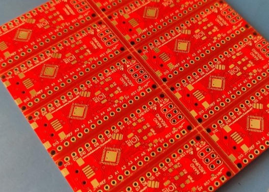
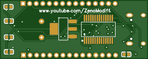
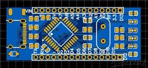
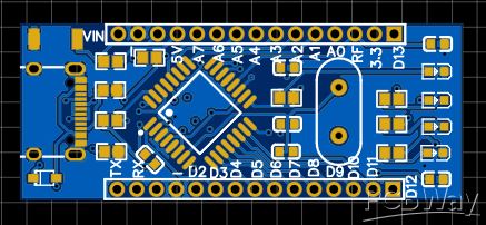
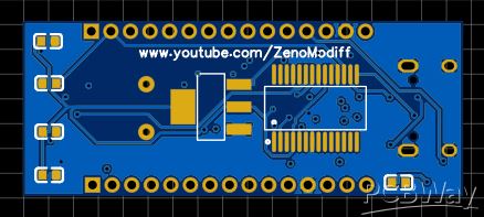
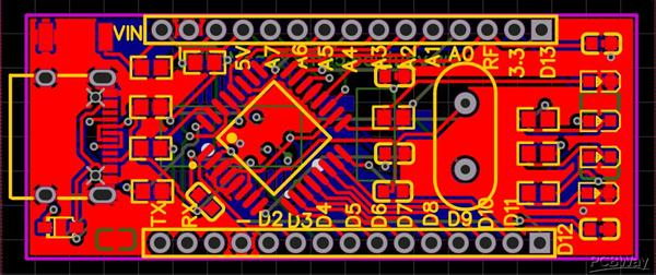
Diy Arduino Nano
This is a simple nano which uses Type C connecter other than the traditional Arduino-nano connector which is more convenient for user
The high-performance Microchip 8-bit AVR? RISC-based microcontroller combines 32 KB ISP Flash memory with read-while-write capabilities, 1 KB EEPROM, 2 KB SRAM, 23 general purpose I/O lines, 32 general purpose working registers, three flexible timer/counters with compare modes, internal and external interrupts, serial programmable USART, a byte-oriented Two-Wire serial interface, SPI serial port, 6-channel 10-bit A/D converter (8-channels in TQFP and QFN/MLF packages), programmable watchdog timer with internal oscillator, and five software selectable power saving modes. The device operates between 1.8-5.5 volts.
By executing powerful instructions in a single clock cycle, the device achieves throughputs approaching one MIPS per MHz, balancing power consumption and processing speed.
The ATmega328 is a single-chip microcontroller created by Atmel in the megaAVR family (later Microchip Technology acquired Atmel in 2016). It has a modified Harvard architecture 8-bit RISC processor core.ATmega328 is an Advanced Virtual RISC (AVR) microcontroller. It supports 8-bit data processing. ATmega-328 has 32KB internal flash memory.
ATmega328 has 1KB Electrically Erasable Programmable Read-Only Memory (EEPROM). This property shows if the electric supply supplied to the micro-controller is removed, even then it can store the data and can provide results after providing it with the electric supply. Moreover, ATmega-328 has 2KB Static Random Access Memory (SRAM). Other characteristics will be explained later. ATmega 328 has several different features which make it the most popular device in today’s market. These features consist of advanced RISC architecture, good performance, low power consumption, real timer counter having separate oscillator, 6 PWM pins, programmable Serial USART, programming lock for software security, throughput up to 20 MIPS etc. Further details about ATmega 328 will be given later in this section.
ATmega328 is an 8-bit, 28-Pin AVR Microcontroller, manufactured by Microchip, follows RISC Architecture and has a flash-type program memory of 32KB.
Atmega328 is the microcontroller, used in basic Arduino boards i.e Arduino UNO, Arduino Pro Mini and Arduino Nano.
It has an EEPROM memory of 1KB and its SRAM memory is 2KB.
It has 8 Pins for ADC operations, which all combine to form PortA ( PA0 – PA7 ).
It also has 3 built-in Timers, two of them are 8 Bit timers while the third one is 16-Bit Timer.
You must have heard of Arduino UNO, UNO is based on atmega328 Microcontroller. It’s UNO’s heart. It operates ranging from 3.3V to 5.5V but normally we use 5V as a standard.
Its excellent features include cost-efficiency, low power dissipation, programming lock for security purposes, real timer counter with separate oscillator.
It’s normally used in Embedded Systems applications. You should have a look at these Real Life Examples of Embedded Systems, we can design all of them using this Microcontroller.
Power
The Arduino Nano can be powered via the Mini-B USB connection, 6-20V unregulated external power supply (pin 30), or 5V regulated external power supply (pin 27). The power source is automatically selected to the highest voltage source.
Memory
The ATmega328 has 32 KB, (also with 2 KB used for the bootloader. The ATmega328 has 2 KB of SRAM and 1 KB of EEPROM.
Input and Output
Each of the 14 digital pins on the Nano can be used as an input or output, using pinMode(), digitalWrite(), and digitalRead() functions. They operate at 5 volts. Each pin can provide or receive a maximum of 40 mA and has an internal pull-up resistor (disconnected by default) of 20-50 kOhms. In addition, some pins have specialized functions:
Serial: 0 (RX) and 1 (TX). Used to receive (RX) and transmit (TX) TTL serial data. These pins are connected to the corresponding pins of the FTDI USB-to-TTL Serial chip.
External Interrupts: 2 and 3. These pins can be configured to trigger an interrupt on a low value, a rising or falling edge, or a change in value. See the attachInterrupt() function for details.
PWM: 3, 5, 6, 9, 10, and 11. Provide 8-bit PWM output with the analogWrite() function.
SPI: 10 (SS), 11 (MOSI), 12 (MISO), 13 (SCK). These pins support SPI communication, which, although provided by the underlying hardware, is not currently included in the Arduino language.
LED: 13. There is a built-in LED connected to digital pin 13. When the pin is HIGH value, the LED is on, when the pin is LOW, it's off.
The Nano has 8 analog inputs, each of which provide 10 bits of resolution (i.e. 1024 different values). By default they measure from ground to 5 volts, though is it possible to change the upper end of their range using the analogReference() function. Analog pins 6 and 7 cannot be used as digital pins. Additionally, some pins have specialized functionality:
I2C: A4 (SDA) and A5 (SCL). Support I2C (TWI) communication using the Wire library (documentation on the Wiring website).
There are a couple of other pins on the board:
AREF. Reference voltage for the analog inputs. Used with analogReference().
Reset. Bring this line LOW to reset the microcontroller. Typically used to add a reset button to shields which block the one on the board.
Communication
The Arduino Nano has a number of facilities for communicating with a computer, another Arduino, or other microcontrollers. The ATmega328 provide UART TTL (5V) serial communication, which is available on digital pins 0 (RX) and 1 (TX). An FTDI FT232RL on the board channels this serial communication over USB and the FTDI drivers (included with the Arduino software) provide a virtual com port to software on the computer. The Arduino software includes a serial monitor which allows simple textual data to be sent to and from the Arduino board. The RX and TX LEDs on the board will flash when data is being transmitted via the FTDI chip and USB connection to the computer (but not for serial communication on pins 0 and 1). A SoftwareSerial library allows for serial communication on any of the Nano's digital pins. The ATmega328 also support I2C (TWI) and SPI communication. The Arduino software includes a Wire library to simplify use of the I2C bus. To use the SPI communication, please see ATmega328 datasheet.
Programming
The Arduino Nano can be programmed with the Arduino software (download). Select "Arduino Duemilanove or Nano w/ ATmega328" from the Tools > Board menu (according to the microcontroller on your board). The ATmega328 on the Arduino Nano comes preburned with a bootloader that allows you to upload new code to it without the use of an external hardware programmer. It communicates using the original STK500 protocol. You can also bypass the bootloader and program the microcontroller through the ICSP (In-Circuit Serial Programming) header using Arduino ISP or similar.
Automatic (Software) Reset
Rather then requiring a physical press of the reset button before an upload, the Arduino Nano is designed in a way that allows it to be reset by software running on a connected computer. One of the hardware flow control lines (DTR) of the FT232RL is connected to the reset line of the ATmega328 via a 100 nanofarad capacitor. When this line is asserted (taken low), the reset line drops long enough to reset the chip. The Arduino software uses this capability to allow you to upload code by simply pressing the upload button in the Arduino environment. This means that the bootloader can have a shorter timeout, as the lowering of DTR can be well-coordinated with the start of the upload. This setup has other implications. When the Nano is connected to either a computer running Mac OS X or Linux, it resets each time a connection is made to it from software (via USB). For the following half-second or so, the bootloader is running on the Nano. While it is programmed to ignore malformed data (i.e. anything besides an upload of new code), it will intercept the first few bytes of data sent to the board after a connection is opened. If a sketch running on the board receives one-time configuration or other data when it first starts, make sure that the software with which it communicates waits a second after opening the connection and before sending this data.
Diy Arduino Nano
*PCBWay community is a shared platform and we are not responsible for any design issues.


- Comments(0)
- Likes(2)
More by Sreeram.zeno
-
 Esp12-F Cluster V1.0
The ESP8266 is a low-cost Wi-Fi microchip, with built-in TCP/IP networking software, and microcontro...
Esp12-F Cluster V1.0
The ESP8266 is a low-cost Wi-Fi microchip, with built-in TCP/IP networking software, and microcontro...
-
 TB6612FNG Motor Driver
The TB6612FNG Motor Driver can control up to two DC motors at a constant current of 1.2A (3.2A peak)...
TB6612FNG Motor Driver
The TB6612FNG Motor Driver can control up to two DC motors at a constant current of 1.2A (3.2A peak)...
-
 Sunny Buddy Solar Charger v1.0
This is the Sunny Buddy, a maximum power point tracking (MPPT) solar charger for single-cell LiPo ba...
Sunny Buddy Solar Charger v1.0
This is the Sunny Buddy, a maximum power point tracking (MPPT) solar charger for single-cell LiPo ba...
-
 Diy 74HC4051 8 Channel Mux Breakout Pcb
The 74HC4051; 74HCT4051 is a single-pole octal-throw analog switch (SP8T) suitable for use in analog...
Diy 74HC4051 8 Channel Mux Breakout Pcb
The 74HC4051; 74HCT4051 is a single-pole octal-throw analog switch (SP8T) suitable for use in analog...
-
 Diy RFM97CW Breakout Pcb
IntroductionLoRa? (standing for Long Range) is a LPWAN technology, characterized by a long range ass...
Diy RFM97CW Breakout Pcb
IntroductionLoRa? (standing for Long Range) is a LPWAN technology, characterized by a long range ass...
-
 ProMicro-RP2040 Pcb
The RP2040 is a 32-bit dual ARM Cortex-M0+ microcontroller integrated circuit by Raspberry Pi Founda...
ProMicro-RP2040 Pcb
The RP2040 is a 32-bit dual ARM Cortex-M0+ microcontroller integrated circuit by Raspberry Pi Founda...
-
 Serial Basic CH340G Pcb
A USB adapter is a type of protocol converter that is used for converting USB data signals to and fr...
Serial Basic CH340G Pcb
A USB adapter is a type of protocol converter that is used for converting USB data signals to and fr...
-
 Mp3 Shield For Arduino
Hardware OverviewThe centerpiece of the MP3 Player Shield is a VS1053B Audio Codec IC. The VS1053B i...
Mp3 Shield For Arduino
Hardware OverviewThe centerpiece of the MP3 Player Shield is a VS1053B Audio Codec IC. The VS1053B i...
-
 MRK CAN Shield Arduino
The CAN-BUS Shield provides your Arduino or Redboard with CAN-BUS capabilities and allows you to hac...
MRK CAN Shield Arduino
The CAN-BUS Shield provides your Arduino or Redboard with CAN-BUS capabilities and allows you to hac...
-
 AVR ISP Programmer
AVR is a family of microcontrollers developed since 1996 by Atmel, acquired by Microchip Technology ...
AVR ISP Programmer
AVR is a family of microcontrollers developed since 1996 by Atmel, acquired by Microchip Technology ...
-
 Diy Arduino mega Pcb
The Arduino Mega 2560 is a microcontroller board based on the ATmega2560. It has 54 digital input/ou...
Diy Arduino mega Pcb
The Arduino Mega 2560 is a microcontroller board based on the ATmega2560. It has 54 digital input/ou...
-
 Max3232 Breakout Board
MAX3232 IC is extensively used for serial communication in between Microcontroller and a computer fo...
Max3232 Breakout Board
MAX3232 IC is extensively used for serial communication in between Microcontroller and a computer fo...
-
 Line Follower Pcb
The Line Follower Array is a long board consisting of eight IR sensors that have been configured to ...
Line Follower Pcb
The Line Follower Array is a long board consisting of eight IR sensors that have been configured to ...
-
 HMC6343 Accelerometer Module
The HMC6343 is a solid-state compass module with tilt compensation from Honeywell. The HMC6343 has t...
HMC6343 Accelerometer Module
The HMC6343 is a solid-state compass module with tilt compensation from Honeywell. The HMC6343 has t...
-
 RTK2 GPS Module For Arduino
USBThe USB C connector makes it easy to connect the ZED-F9P to u-center for configuration and quick ...
RTK2 GPS Module For Arduino
USBThe USB C connector makes it easy to connect the ZED-F9P to u-center for configuration and quick ...
-
 Arduino Explora Pcb
The Arduino Esplora is a microcontroller board derived from the Arduino Leonardo. The Esplora differ...
Arduino Explora Pcb
The Arduino Esplora is a microcontroller board derived from the Arduino Leonardo. The Esplora differ...
-
 Diy Stepper Motor Easy Driver
A motor controller is a device or group of devices that can coordinate in a predetermined manner the...
Diy Stepper Motor Easy Driver
A motor controller is a device or group of devices that can coordinate in a predetermined manner the...
-
 Diy Arduino Pro Mini
The Arduino Pro Mini is a microcontroller board based on the ATmega168 . It has 14 digital input/out...
Diy Arduino Pro Mini
The Arduino Pro Mini is a microcontroller board based on the ATmega168 . It has 14 digital input/out...
-
IoT Indoor system with ESP32 to monitor Temperature, Humidity, Pressure, and Air Quality
288 0 1 -
Naruto Multi-color PCB printed with UV technology
113 2 1 -
-
-
-


